EM 1110-2-1100 (Part II)
30 Apr 02
area to the vessel wetted cross section area (known as the section coefficient), and the ratio of the water depth
to the vessel draft. Other factors that might affect sinkage and trim include the vessel hull geometry, the at-
rest trim of the vessel, the cross-section geometry of the channel, the sailing line of the vessel relative to the
centerline of the channel, vessel acceleration or deceleration, the presence of currents in the channel, and the
passing of other vessels in the channel.
(c) A wide variety of analytical, quasi-analytical, and empirical methods for predicting vessel sinkage
and a few for predicting vessel trim have been published (Garthune et al. 1948, Constantine 1960, Tuck 1966,
Tothill 1967, Sharp and Fenton 1968, Dand and Furgeson 1973, McNown 1976, Beck 1977, Gates and
Herbich 1977, Eryuzlu and Hausser 1978, Blauuw and van der Knapp 1983, Ferguson and McGregor 1986).
The earliest and most basic approach to predicting vessel sinkage employs the one-dimensional energy and
continuity equations. This approach gives generally acceptable results for uniform channels and vessel hull
geometries that are not too irregular. The continuity and energy equations are written between a point ahead
of the vessel and a point at the vessel midsection. The water surface drawdown is thus calculated and
assumed equal to the vessel sinkage. The results for a rectangular channel cross section are presented below;
for a trapezoidal channel cross section see Tothill (1967) and for a parabolic channel cross section, see
McNown (1976).
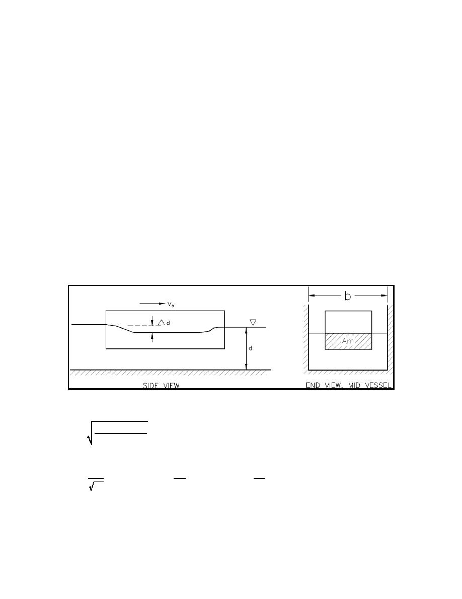
(d) Consider a vessel in a channel with the relevant dimensions as defined in Figure II-7-42 where b is
the channel width, Am is the vessel's midsection wetted cross-section area, the undisturbed water depth is d,
and the vessel drawdown is ∆d. Vs and g are the vessel speed and the acceleration of gravity as defined
earlier. The continuity and energy equations in terms of the Froude number F, dimensionless drawdown D,
and vessel blockage ratio S are solved by
Figure II-7-42. Definition of terms, vessel drawdown
2 D (1 & D & S ) 2
F'
(II-7-24)
1 & (1 & D & S ) 2
where
VS
Am
∆d
F'
D'
S'
bd
d
gd
(e) Figure II-7-43 plots F versus D for selected values of S. Given the channel cross-section dimensions,
the water depth, the vessel speed, and the midsection wetted cross-section area of the vessel, D can be
determined from the figure. This, in turn, yields the water surface drawdown ∆d, which is taken as the vessel
sinkage.
II-7-60
Harbor Hydrodynamics


 Previous Page
