EM 1110-2-1100 (Part II)
30 Apr 02
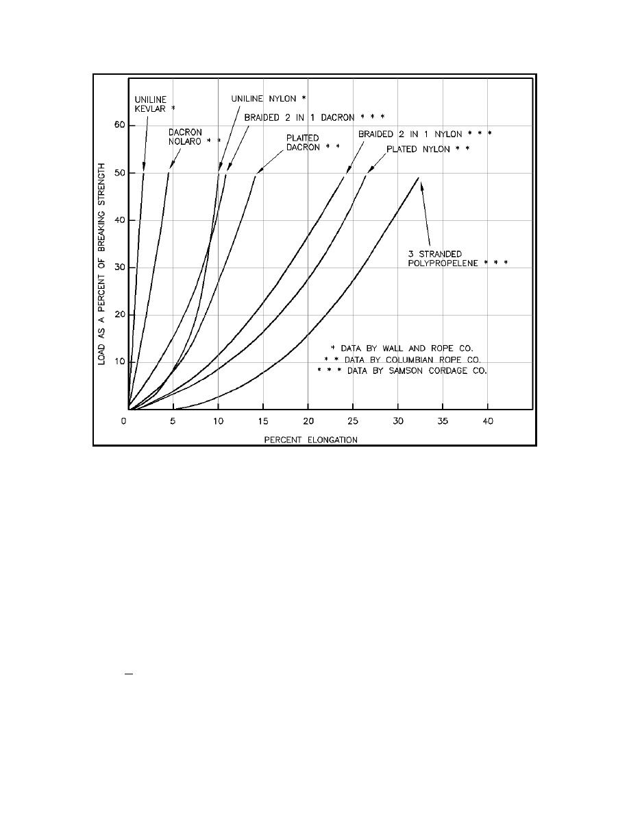
Figure II-7-45. Mooring fiber rope elongation curves
(6) Mooring forces.
(a) Design of any of these systems requires that the primary hydrodynamic loads on the vessel caused
by the wind, currents, and waves be determined, usually on a probabilistic basis. Other loads that may be
important in certain situations are ice forces and forces induced by passing vessels. The appropriate forces
are employed in a dynamic analysis of the mooring system to determine expected loads in the mooring lines
and on the fender systems. This analysis can be done by a physical model study or by a computer simulation
of the system dynamics equations (see Bruun (1989) and Gaythwaite (1990)). Detailed discussions of the
primary vessel mooring forces, those caused by the wind, currents, and waves, can be found in Tsinker
(1986), Bruun (1989), and Gaythwaite (1990).
(b) The wind load is determined from the usual drag equation
1
2
ρa CD A V10
Fw '
(II-7-31)
2
where Fw is the drag force due to the wind, ρa is the air density, CD is a drag coefficient, A is the projected area
of the vessel above the waterline, and V10 is the wind speed at the standard elevation of 10 m above the
water's surface.
Harbor Hydrodynamics
II-7-67


 Previous Page
