
EM 1110-2-1100 (Part II)
30 Apr 02
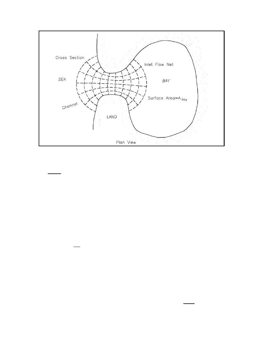
Figure II-6-21.
Inlet flow net
116 n 2
f'
(II-6-16)
R 1/3
(b) It seems reasonable to assume a constant n for an inlet in sand rather than a uniform f value. For
open channels in hard-packed smooth sand, Chow (1959) recommends an n value of 0.020 (in English units,
or 0.016 in SI). Since inlets often have rippled or duned bottoms, which generally increase frictional
resistance, a higher n value might be expected, for instance between 0.025 and 0.030 (English units or 0.021
and 0.025, SI). Using an estimated value of n = 0.0275 (English units or 0.0225 SI), a friction factor defined
by f = 0.088/R1/3 (English units, R in feet, or 0.059/R1/3, SI, R in meters) is recommended for use in the
equation for K.
Jarrett (1975) examined the friction aspect of Keulagan K (Equation II-6-4) and defined F, inlet impedance,
as
fL
F ' ken % kex %
(II-6-17)
4R
with ken, kex, f, and L as defined earlier, and hydraulic radius R measured at the minimum cross section of the
inlet. Figure II-6-22 plots inlet impedance against the ratio of inlet length to the 4/3 power of hydraulic radius
for four ratios of minimum cross-section inlet width to hydraulic radius. These curves can be used for
determining F.
(4) Inlet length. Inlet length is one of the more difficult parameters to define. The following
standardized method is recommended to determine inlet length. On a detailed bathymetric chart, beginning
in deep water just offshore from the inlet, mark the points of maximum depth moving across the bar, through
the inlet, and into the bay. The bayward end point should be seaward of any major division of the inlet
II-6-22
Hydrodynamics of Tidal Inlets

 Previous Page
