EM 1110-2-1100 (Part II)
30 Apr 02
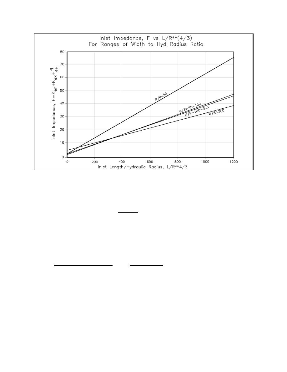
Figure II-6-22. Inlet impedance (F) versus the ratio of inlet length to inlet hydraulic radius to the 4/3 power (l/R4/3)
for various inlet width to inlet hydraulic radius ratios, W/R
channel. Connect these points of maximum depth with a series of straight lines to define the thalweg of the
channel. Construct a plot of depth versus distance from the oceanward point along the thalweg. Define inlet
length as the distance between the depth minimum oceanward of the deepest part of the inlet and the depth
minimum bayward of the deepest part. Where the channel does not shoal near either end, the limit of the inlet
must be estimated by considering the relationship of the inlet to adjacent beaches, i.e., draw a line
perpendicular to the thalweg from MSL on one shoulder of the inlet to MSL on the other, and assume its
intersection with the thalweg defines the channel end.
(5) Hydraulic radius. For a given cross-section area, the corresponding value of R should be computed
from
Aavg
Aavg
.
R'
(II-6-18)
Average Wetted Perimeter
Average Width
These methods are intended to provide a simplified approach to understanding inlet hydraulics in a rapid
manner. If possible, field data should be examined to correlate with existing condition calculations,
adjustments made to various controlling parameters, and calculations reiterated until reasonable results are
achieved. Then calculations may proceed to evaluate design changes. It must be remembered that for
extreme events, when wind and wave breaking may be significant factors influencing the hydrodynamics of
the inlet system, more sophisticated approaches will be needed. Even a relatively well-behaved inlet is only
approximately represented by these approaches, but much insight can be gained by these techniques.
Hydrodynamics of Tidal Inlets
II-6-23


 Previous Page
