EM 1110-2-1100 (Part II)
30 Apr 02
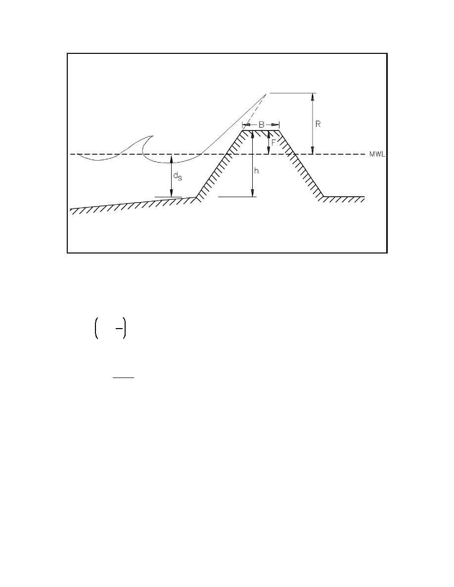
Figure II-7-18.
Schematic breakwater profile and definition of terms
(c) Seelig presented a simple formula for estimating the wave transmission coefficient for subaerial stone
mound breakwaters, which is valid for both monochromatic and irregular waves:
F
Ct ' C 1 &
(II-7-2)
R
(d) The coefficient C is given by
0.11B
C ' 0.51 &
(II-7-3)
h
where B is the structure crest width and h is the crest elevation above the bottom (see Figure II-7-18). It is
recommended that Equation II-7-2 be applied to the relative depth (ds/gT2) range of 0.03 to 0.006 and
Equation II-7-3 to the range of B/h between 0 and 3.2, because these are the ranges of experimental data
employed to develop the equations.
(e) The report by Seelig (1980) contains laboratory results for 19 different breakwater cross-section
geometries. Specific results for one or more of these geometries may closely relate to the prototype structure
being analyzed. For irregular waves, the wave transmission coefficients were defined in terms of the incident
and transmitted spectral energies.
(2) Rubble-mound structures-submerged.
(a) Rubble-mound structures having their crest at or below the mean water level have seen increasing
use recently. Often, they simply consist of a homogeneous wide-graded mass of stone. A functional
II-7-20
Harbor Hydrodynamics


 Previous Page
