EM 1110-2-1100 (Part II)
30 Apr 02
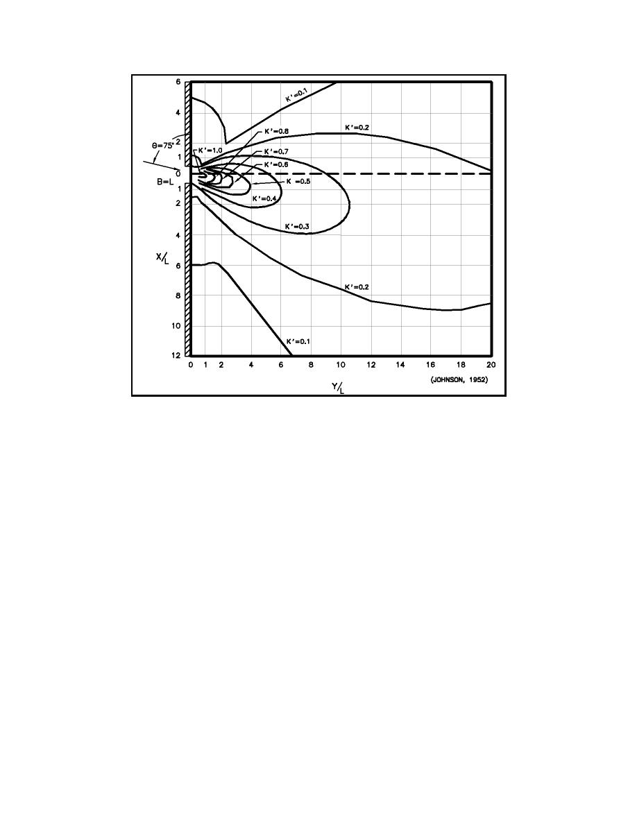
Figure II-7-12. Diffraction for a breakwater gap of one wavelength width where φ =
75 deg
depth changes commence. Hopefully, this will be a distance of at least three or four wavelengths from the
entrance. This diffraction analysis will define the wave heights and crest orientation at the point where
significant shoaling-refraction effects commence. From this point landward, a refraction-shoaling analysis
using the procedures described in Part II-3 can be used to carry the wave to the point of breaking or
interaction with a land boundary.
f.
Combined diffraction - reflection in harbors.
(1) A computer program for dealing with combined diffraction and reflection by a vertical wedge has
been developed by Seelig (1979, 1980) and is available in the Automated Coastal Engineering System
(ACES) (Leenknecht et al. 1992). This package estimates wave height modifications due to combined
diffraction and reflection caused by a structure. It has the ability to simulate a single straight, semi-infinite
breakwater, corners of docks, and rocky headlands. Assumptions include monochromatic, linear waves, and
constant water depth.
(2) The user has the ability to vary the wedge angle from 0 to 180 deg, where 0 deg would represent the
case of a single straight, semi-infinite breakwater and 90 deg, the corner of a dock.
(3) The required input includes incident wave height, wave period, water depth, wave angle, wedge
angle, and X and Y coordinates (location of desired calculation). The range of X and Y should be limited
to plus or minus 10 wavelengths.
Harbor Hydrodynamics
II-7-13


 Previous Page
