EM 1110-2-1100 (Part II)
30 Apr 02
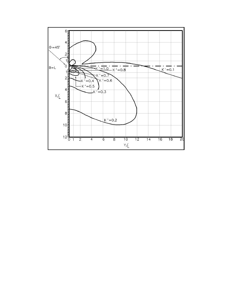
Figure II-7-10.
Diffraction for a breakwater gap of one wavelength width where φ =
45 deg
(3) The results for waves approaching perpendicular to a semi-infinite breakwater are shown in
Figure II-7-13 where the solid lines define values of KNe and the dashed lines are the ratio of peak spectral
period for the diffracted to incident waves. The results for waves approaching normal to a breakwater gap
are shown in Figures II-7-14 to II-7-17, where the ratio of gap width to incident wavelength varies from 1
to 8. Note that these diagrams are normalized by dividing by both the gap width and the wavelength, so two
different horizontal scales are given for each case. Also, the left-hand side gives the peak period ratio and
the right-hand side gives values of KNe.
(4) The spectral diffraction diagrams for the semi-infinite breakwater show a small change in the peak
period ratio as the waves extend into the breakwater lee. (For monochromatic waves the wave period would
not change.) The same holds for the breakwater gap. For the semi-infinite breakwater the values of KNe are
generally higher than the equivalent values of KNfor monochromatic waves. For a breakwater gap, the spatial
variation of KNe values is smoothed out by the directional spread of the incident waves. That is, there is less
variation in KNe values for the spectral case than in KN for the monochromatic case. For waves approaching
a breakwater gap at some oblique angle, the imaginary equivalent gap approach depicted in Figure II-7-6 can
be used.
(5) Thus, if the one-dimensional or directional spectrum for the design waves is known at a harbor
entrance, Equation II-7-1 can be used with the monochromatic wave diffraction diagrams to more effectively
evaluate wave diffraction in the harbor. The spectrum can be broken into a number of direction and/or
frequency components, each component can be analyzed as a diffracting monochromatic wave, and the results
can be recombined using Equation II-7-1.
Harbor Hydrodynamics
II-7-11


 Previous Page
