EM 1110-2-1100 (Part II)
30 Apr 02
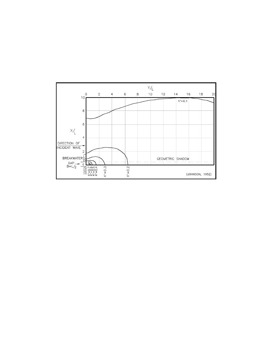
(b) Penny and Price (1952) developed a solution for the diffraction of normally incident waves passing
through a structure gap by superimposing the solutions for two mirror image semi-infinite breakwaters.
Johnson (1952) employed their solution to develop diagrams that give diffraction coefficients for gap
widths (B) that are between one half and five times the incident wavelength. The lateral coordinates (x,y) are
again nondimensionalized by dividing by the wavelength. Figure II-7-5 is an example of one of the diagrams
Johnson (1952) developed. Only one half of the pattern is shown; the other half would be a mirror image.
The reader is referred to Johnson (1952) and the Shore Protection Manual (1984) when dealing with gap
widths other than 0.5 wavelength.
Figure II-7-5. Contours of equal diffraction coefficient gap width = 0.5 wavelength
(B/L = 0.5)
(c) It may be necessary to know the wave crest orientation in the diffraction zone. Up to about six
wavelengths beyond the gap, it is recommended (Shore Protection Manual 1984) that the wave crest position
be approximated by two arcs that are centered on the two breakwater tips (as for a semi-infinite breakwater)
and that the arcs be connected by a smooth curve that is approximately a circular arc centered on the
midpoint of the gap. Beyond eight wavelengths, the crest position may be approximated by a single circular
arc centered on the gap midpoint.
(d) The waves approaching a breakwater gap will usually not approach in a direction normal to the gap.
Johnson (1952) found that the results presented above for normally incident waves can be used as an
approximation for oblique waves by employing an imaginary equivalent gap having an orientation and width
B' as defined in Figure II-7-6. Carr and Stelzriede (1952) employed a different analytical approach than that
developed by Sommerfeld (1896) and also developed diffraction pattern solutions for barrier gaps that are
small compared to the incident wavelength. Johnson (1952) used their approach to develop diffraction
coefficient diagrams for a range of wave approach angles and a gap width equal to one wavelength. These
are shown in Figures II-7-7 through II-7-12 for approach angles between 0 and 75 deg.
(e) Often, harbor entrance geometries will be different from the semi-infinite and gap geometries
presented above. Still, approximate but useful results can be achieved by applying these solutions with some
ingenuity in bracketing the encountered entrance geometry and interpolating results.
Harbor Hydrodynamics
II-7-7


 Previous Page
