EM 1110-2-1100 (Part II)
30 Apr 02
G
where V = average horizontal velocity at a node
(5) For example, when H = 1 ft, T1 = 200 sec, and d = 30 ft, the maximum horizontal velocity and particle
excursion are Vmax = 0.5 ft/sec and X = 33 ft.
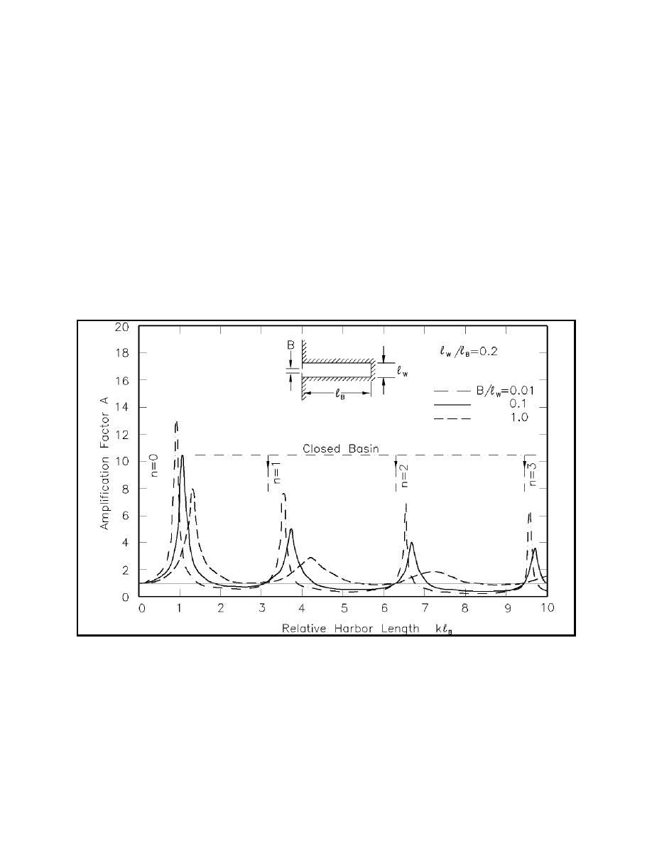
(6) The resonant response of the simple rectangular harbor, presented by Ippen and Goda (1963) in terms
of the amplification factor A (assuming no viscous dissipation) and the relative harbor length kR, where k =
2π/L, illustrates other important aspects of harbor oscillation. The amplification factor for harbor oscillations
is traditionally defined as the ratio of wave height along the back wall of the harbor to standing wave height
along a straight coastline (which is twice the incident wave height). The response curve for a long, narrow
harbor is given in Figure II-7-30. The left portion of the curve resembles that for the mechanical analogy in
Figure II-7-26. Resonant peaks for higher order modes are also shown. The three curves correspond to a
fully open harbor and two partially open harbors with different degrees of closure. The kR value at resonance
decreases as the relative opening width decreases. It is bounded by the value for a closed basin, also shown
in the figure. Amplification factors for the inviscid model are upper bounds on those experienced in a real
harbor. Because amplification factor decreases at each successive higher order mode, simple analysis
methods often focus only on the lowest order modes.
Figure II-7-30. Theoretical response curves of symmetrical, narrow, rectangular harbor (Raichlen (1968);
after Ippen and Goda (1963))
(7) Practical guidance for assessing the strength and period of the first two resonant modes in a partially
enclosed rectangular harbor with a symmetric entrance is given in Figure II-7-31. A wide range of relative
harbor widths (aspect ratios, b/R) and relative entrance widths (d/b) is represented. The kR values can be
converted to resonant periods by
II-7-38
Harbor Hydrodynamics


 Previous Page
